
Desktop CNC Mill
Overview
Over the summer of 2022, I set out to make my own desktop CNC mill to machine small aluminum parts. Originally, I wanted it to be about the size of a 3D printer, and cost around $500. However, after researching similar projects and a few design iterations, I realized that I couldn’t really make a machine worth $500 for $500. My costs are also way higher off campus during the summer without access to a machine shop and free stock.
Although nothing was built, designing these mills was incredibly fun. This was my first time designing specifically for rigidity. The electronics and controls of this project were also completely foreign to me, so designing the system and sourcing components was tedious, but good exposure.
This was also a trial-by-fire initiation to Solidworks, which I love, and is now my preferred CAD package. All parts in the assembly were defined by master sketches in the front, right, and top planes. This method was very robust, and it’s how I’m doing all my assemblies from now on.
The right way to do this project, is to make something significantly larger for $3,000-$5,000, which would also ideally be capable of cutting steel. I would like to attempt this before I graduate and lose access to Purdue’s machine shop.
Electronics box, brackets, and gusset plates not shown.
Electronics
I was using a 500 Watt spindle with a built in ER-11 collet. I was using Nema-17 steppers to drive my 3 axes on lead screws (not ball screws becuase budget). Surprisingly, they are able to handle my expected cutting forces while staying under the stepper drivers’ current limit. The stepper drivers were integrated in the control board, which was running GRBL 1.1. This machine had two power supplies. One was integrated into the spindle and it’s speed controller, and the other to the control board and steppers. The control board could be wired with one estop button (in addition to a virtual feed hold), but I plannd to add a second estop that cut off both power supplies via two relays as a precaution.
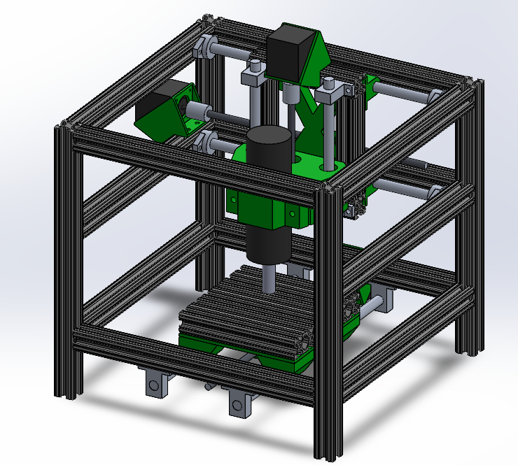
V1
Version 1 is similar to a 3D printer design. It was inspired by desktop CNC mills in the $3,000-$5,000 range, like the Carbide 3D Nomad or a Bantam.
This design had the table travel in Y, and the Z axis assembly travel in X above the table. Everything was contained in an aluminum extrusion frame, with 3D printed motor mounts, brackets, and gusset plates. The axis moved on 12 mm linear rods.
This design had a few large flaws. For one, having the structural frame enclosing the machine made it easy to mount an enclosure, but it was not very rigid, or efficient use of aluminum, since the frame struts were unnecessarily large. Second, linear rods are not the mopst rigid linear motion system, althpugh they are cheap. Similar designs, such as the commercial mills listed above, overcome these rigidity issues with steel frames, and ridiculously thick linear rods. Those solutions however, are not within my budget (at least off campus), since they are not an efficient use of materials.
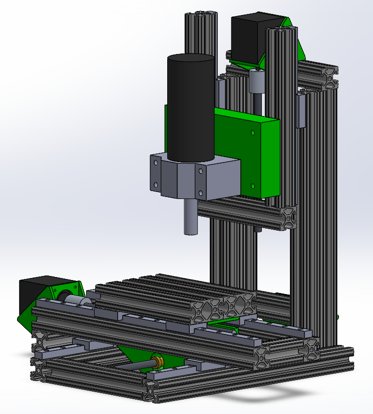
V2
Version 2 has a few major upgrades from Version 1.
It is a knee mill configuration, similar to large production CNC mills, with the table moving in X and Y, and the Z axis on a tower. The main advantage of a knee mill design, as opposed to a 3d printer or cnc router design, is that the structural frame is smaller than the machine, as opposed to a frame that encloses the entire machine. This minimizes the length of each beam in the frame, which improves rigidity a lot. The bed is also no longer square, it’s rectangular, which minimizes Z axis overhang for without significantly reducing the cutting volume. The linear motion system has been upgraded to linear rails with carriages, for rigidity.
V3
V3 of this machine would feature the following improvements:
-
Replace almost all aluminum extrusion with steel bar. This could be done at very little cost with the resources at school.
-
Replace the cheap spindle with a higher quality spindle that comes with a real VFD. This would be by far the most expensive part, but I’m nervous about the how straight a cheap spindle will be as the bearings wear out.
-
Redesign the Z axis frame with a cross beam that lets me adjust the spindle to be truly normal to the table.
-
Replace the 3d printed spindle mount and table mount with a machined aluminum parts.
-
Add an enclosure for chips and possibly coolant if I can get free polycarbonate.
-
Maybe add a “drip” coolant system, which could be a fish tank pump, dripping coolant onto the spindle. This would require a coolant tray and filter in the bottom of the enclosure, which could be waterjetted polycarbonate sheets and hot glue.