
Fiberglass Tube Defects and Testing
08 Jul 2022
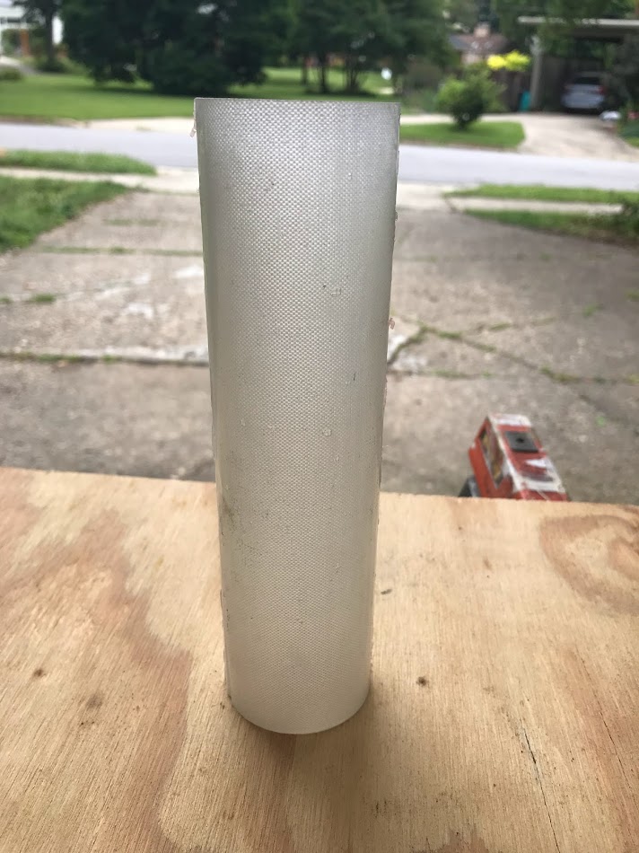
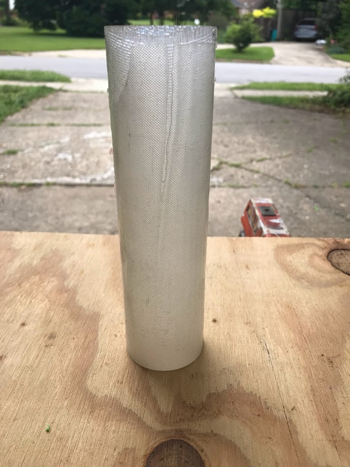
I post processed my interior molded fiberglass tube and tested it for compressive strength. I’ll be detailing the process, as well as analyzing the defects in the tube and their causes.
Post Processing
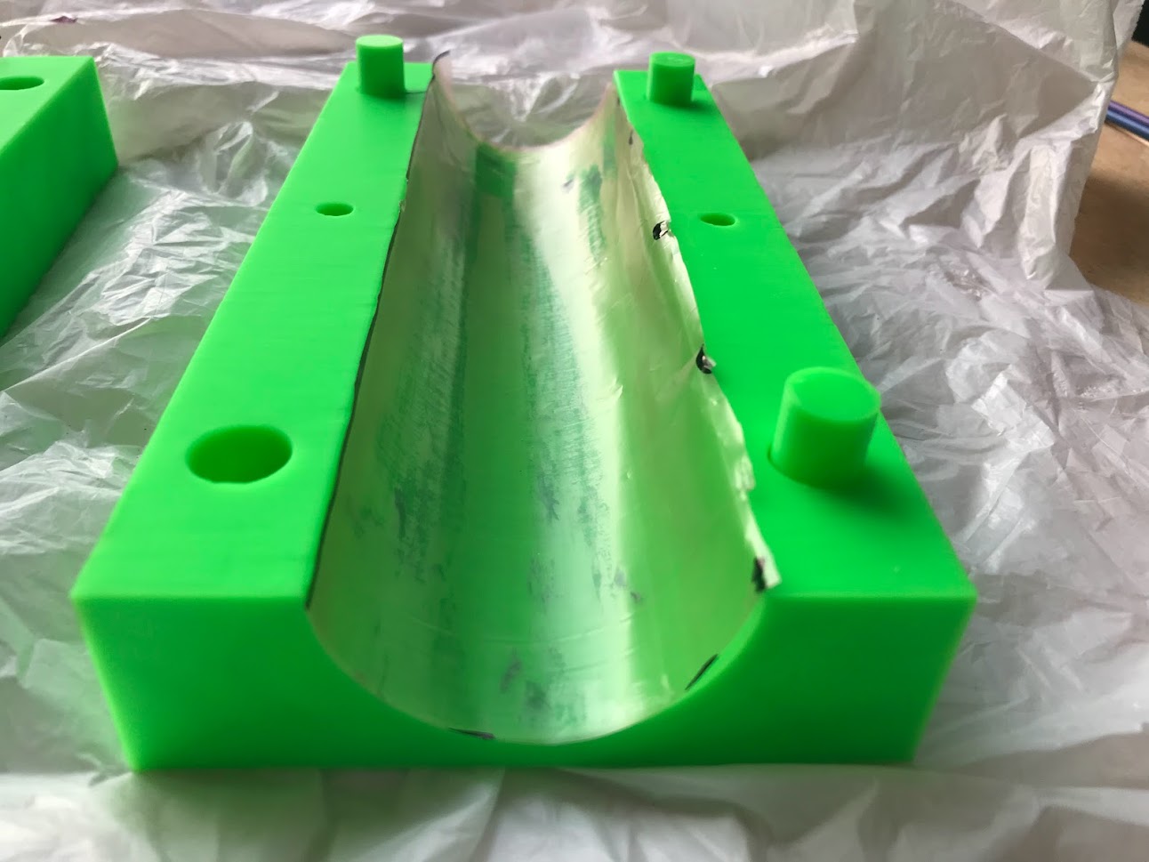
Removing the tube from the mold was pretty easy. Not surprisingly, the two halves of the mold were epoxied together, but they came apart with a chisel without any permanent damage to the mold.
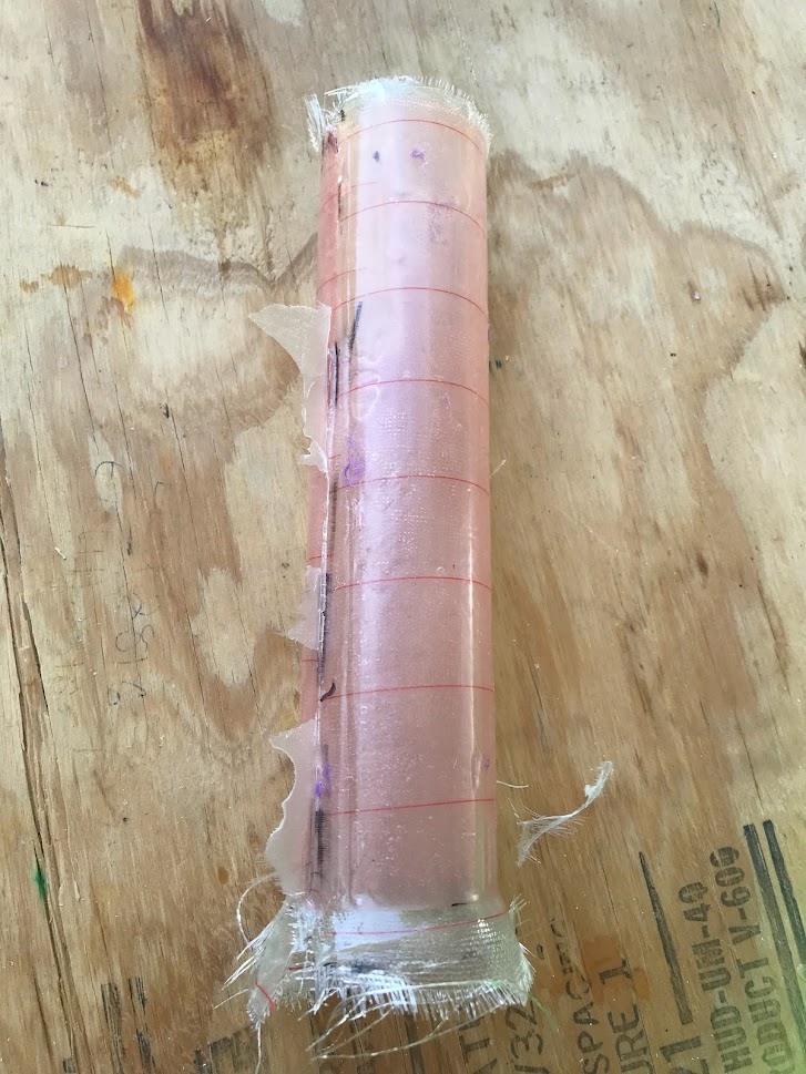
The pink mold release film came off pretty easily, although some of it had been caught in the layers between the seam and couldn’t be removed. There were thin flakes of epoxy that seeped between the two halves of the mold, which I cut off with an exacto knife.
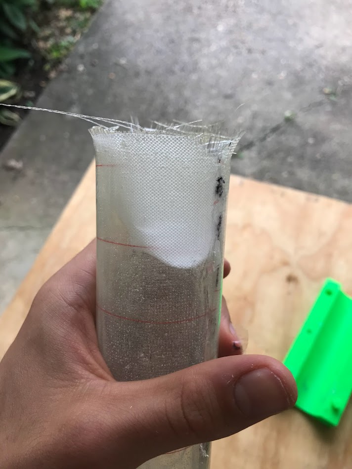
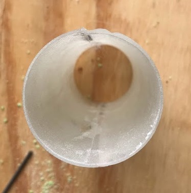
Removing the peel ply from an interior molded tube was difficult. I had intentionally oversized the peel ply so I would have a starting place, but it was still hard because of limited access to the inside of the tube. I was able to get the peel ply off using needle nose pliers and peeling from both sides to meet in the middle. The peel ply definitely limits the max aspect ratio for interior molds.
Additionally, the balloon caused problems with the peel ply On my first tube, I left the deflated balloon in the mold, and when the resin cured, it left a lump of resin on the peel ply, which made it more difficult to remove. I avoided this on later layups by removing the balloons while the resin was still tacky
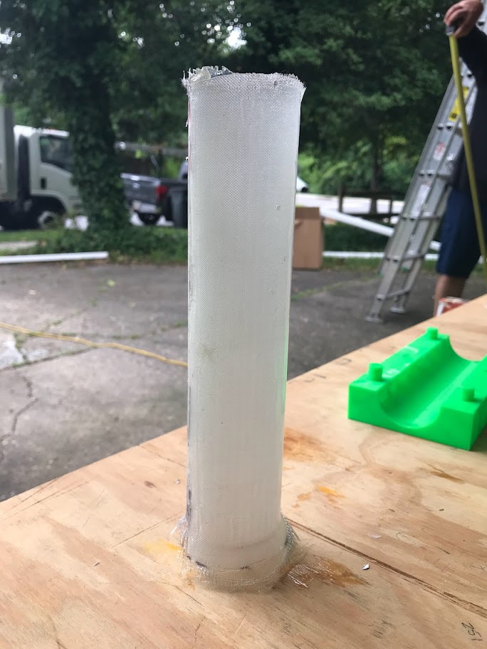
I used a cutting jig that consisted of an adjustable collar that tightens around the tube, disposable faces to guide the saw blade, and a sacrificial cylinder tube to keep the tube circular during cutting. With a handsaw and sanding, I achieved a very flat edge that sat flush with the compressive test jig.
The mandrel wrapped tube came out lumpy due the location of the tape. Even with the mold release film, I couldn’t get it off the mandrel (due to a lack of Will Ipsens), so I abandoned it: rip.
Defects
Let’s talk about defects.
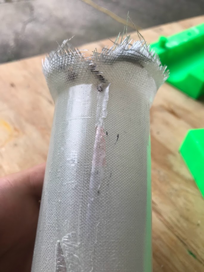
Wet Spots
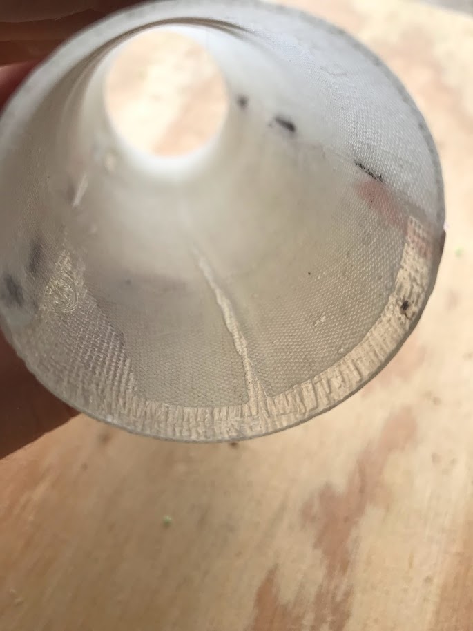
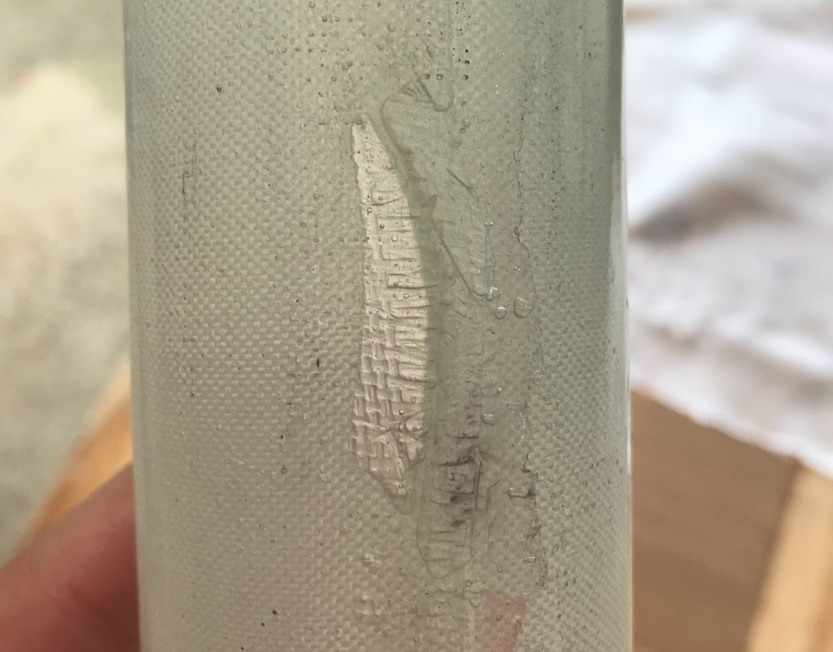
The most noticeable defects are wet spots, which occurred where the peel ply did not laminate to the fiberglass properly to soak up the resin. This happened where the peel ply was wrinkled or not fully compressed. Wet spots appear transparent due to the excess resin and have the appearance of wrinkles, but the fiberglass is not actually wrinkled.
The wet spots only appear on one side of the tube, where I had to apply the peel ply after closing the mold and couldn’t fully smooth it. On the next tube, I’m staggering the peel ply using the same method as the staggered fiberglass to apply all the peel ply before the mold is closed.
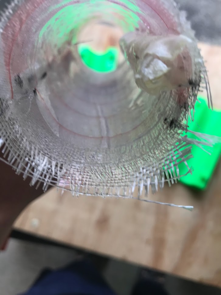
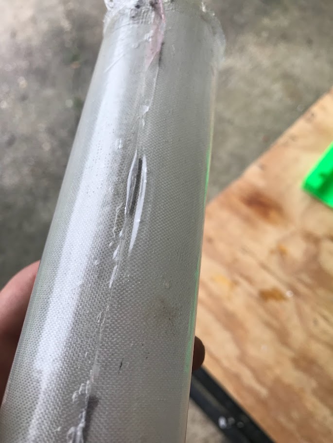
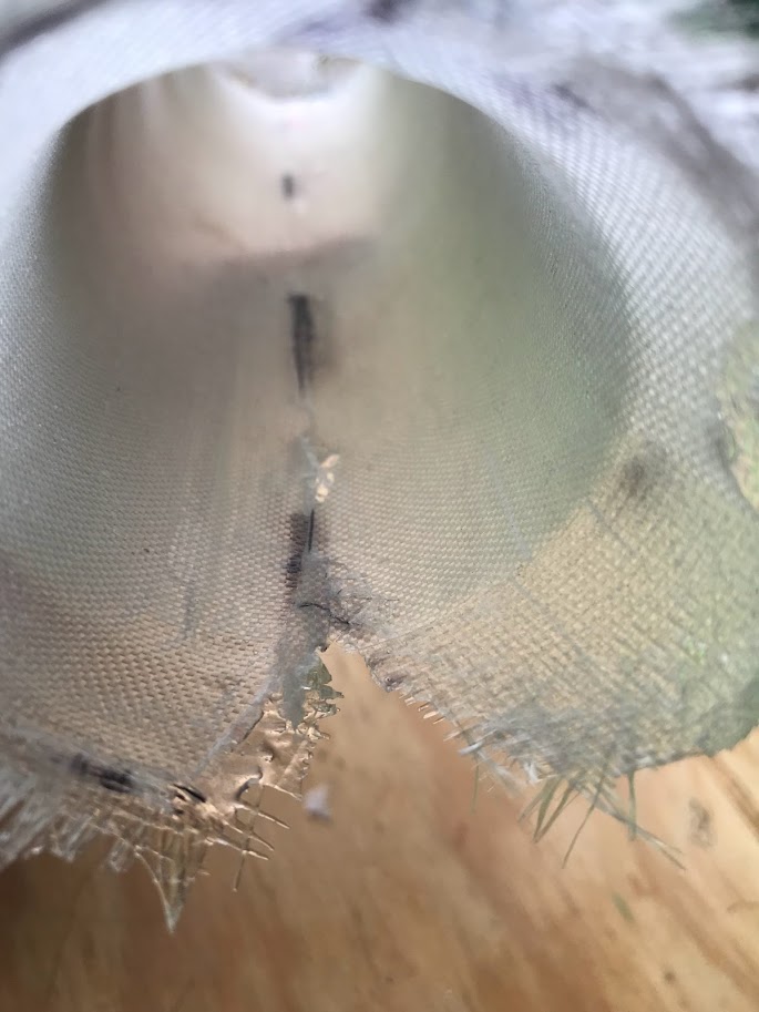
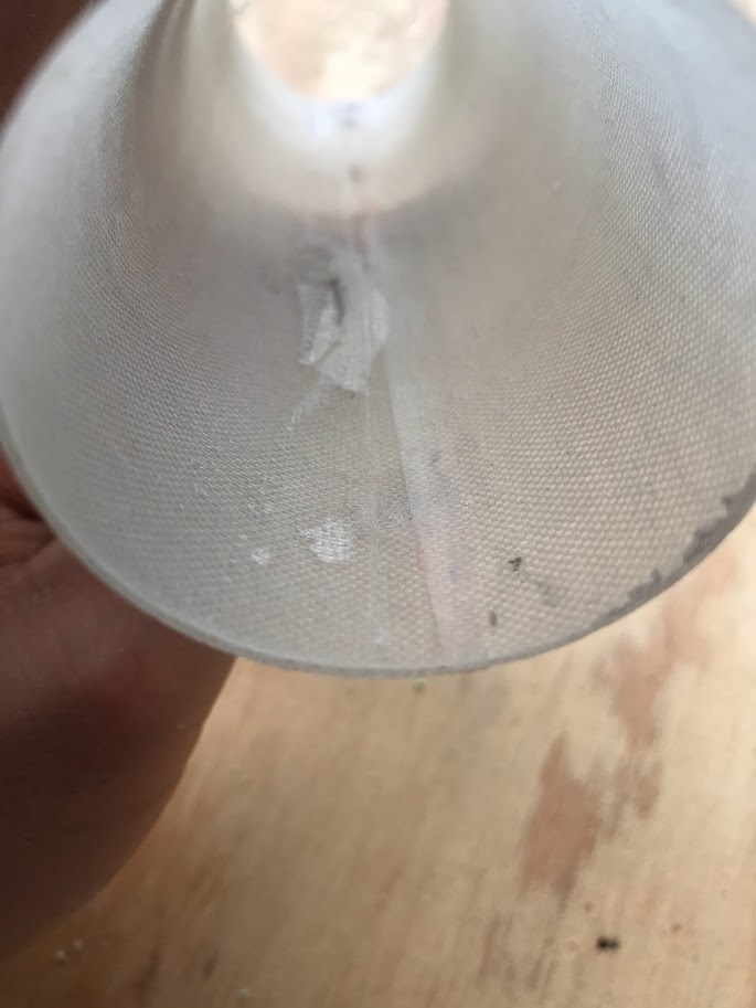
Seams
The most noticeable defect near the seams are large concave wrinkles. I believe they were caused by a preexisting crease in the mold release film, and insufficient compression to smooth them out. They only occur on one side of the tube on one side of the mold, which is the only place that had a crease. On one end of the tube, the seam didn’t fully bond, so I had to cut off about 1/4”.
The seam inside is very clean, and overall I’m happy with the result.
Peel ply is not sitting tight against the mold.
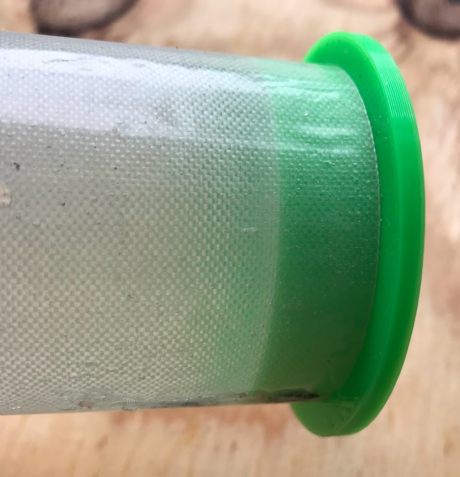
Wrinkles and Finish
The exterior of the tube has a glossy finish. In photos, the surface appears to have ripples, which makes the surface look like it has tiny wrinkles. This is an illusion that has occured on other glossy tubes I’ve made, and it is made worse due to a poor mesh on my 3d printed molds, oops.
Simulation
Ansys simulations predicted to support ~420 lbs in compression. This simulation did not model the seam, which I am working on right now. My conservative prediction was a knockdown factor of 50% due to defects.
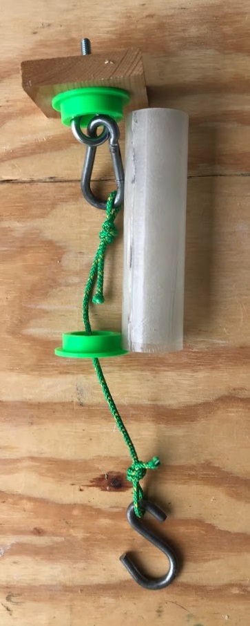
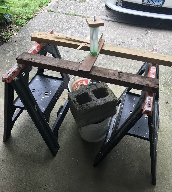
Testing
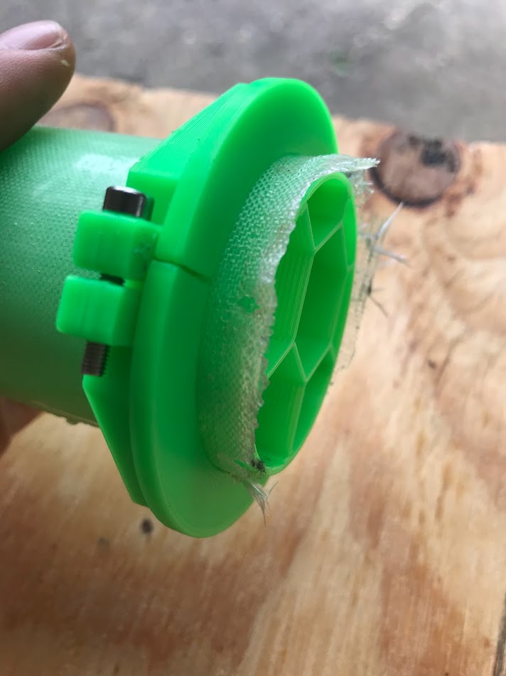
I tested the tube in compression with a setup that used hanging weights to squish the tube. I printed two alignment plates, which centered the load axially on the tube, and provided a hard surface so the fiberglass wasn’t digging into soft wood. The alignment plates had a very tight fit with the tube, so the load was distributed evenly. I hung two alignment plates from the top alignment plate with an eye bolt and parachute cord. The alignment plates were leveled with shims so that the load was axial.
The tube supported 210 lbs of dumbbells, bricks, cinder blocks, and rock salt before I ran out of weights.
Thoughts
This tube showed that a seam in a composite tube can be very strong, and the interior molding method is very promising for use on PSP’s rocket. Defects such as wet spots and mold release film wrinkles stem from a wet layup, and won’t be an issue with prepregs in the future. I’m excited to see the results when I use a real vacuum bag, and not just a balloon.
I will be flying this tube on my L1 rocket, and using this method to make the rest of the airframe.