
Fiberglass Tube Manufacturing
03 Jul 2022
I made interior molded and mandrel wrapped fiberglass tubes to compare the manufacturing difficulty of each method. These were wet layups sized for my L1 rocket’s airframe, but they’re also an early test of manufacturing processes for PSP liquids, which would use prepreg with a vacuum bag.
Both tubes are 8” long, 2” OD tubes with 4 layers of fiberglass at 0 degrees in a wet layup. Both tubes used mold release film, 3D printed tooling, and peel ply on the outermost layer
Interior Molding
I used a method from Easy Composites, where the seam is created by extending the fiberglass on one side of the mold to overlap with fiberglass lower than the other side of the mold. Each layer inward is larger on the extended side or smaller on the lower side, than the last layer, creating astaggered pattern that does not concentrate the seam on one spot. My extended side had each consecutive layer increase by .25”, and my lower side had layer size decrease by .125”, which are similar to the 5 mm and 3 mm increments used by Easy Composites.
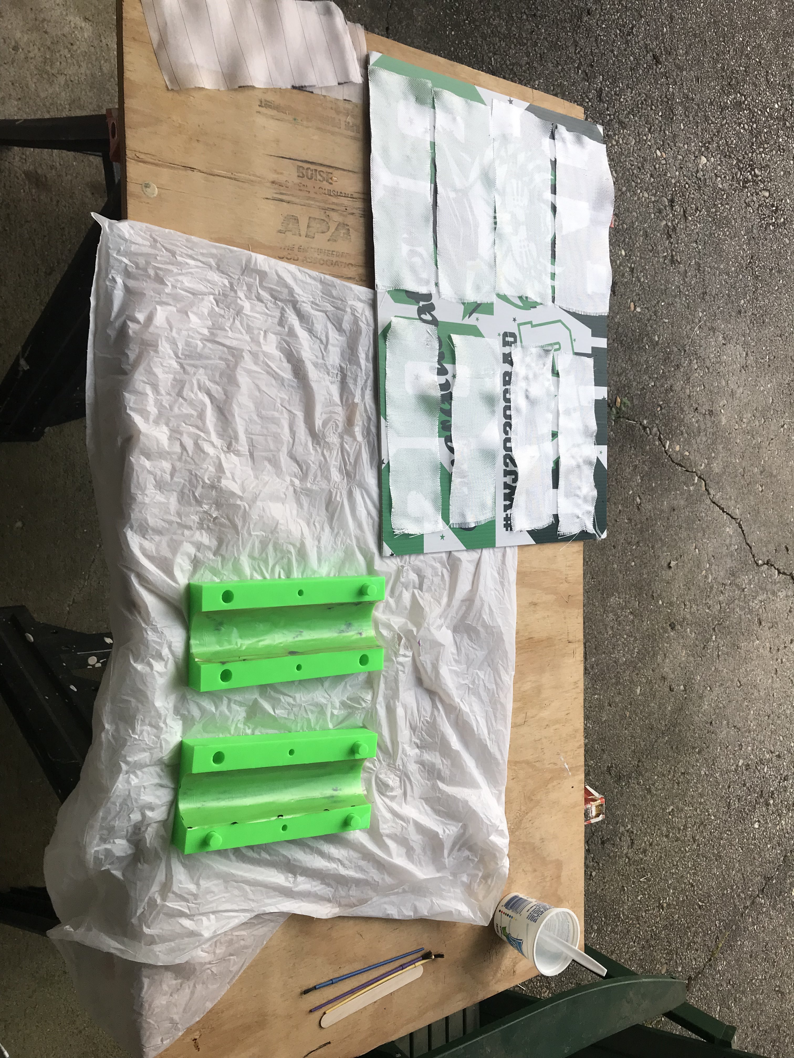
Each layer on each half of the mold is a seperate piece of fiberglass, so for this 4 layer tube, I prepared 8 pieces of fiberglass. I used a method where you pull out one thread to create a cut line that doesn’t cross over threads. I was disappointed by the quality control on Fiberglast’s 4 oz fiberglass, since it had several spots where the weave was stretched. Since it was a plain weave, handling was easy, but achieving decent fiber alignment was very difficult. This is an issue with any wet layup, and can be solved by using prepreg or a tighter weave, as was clear that this fabric was designed for draping.
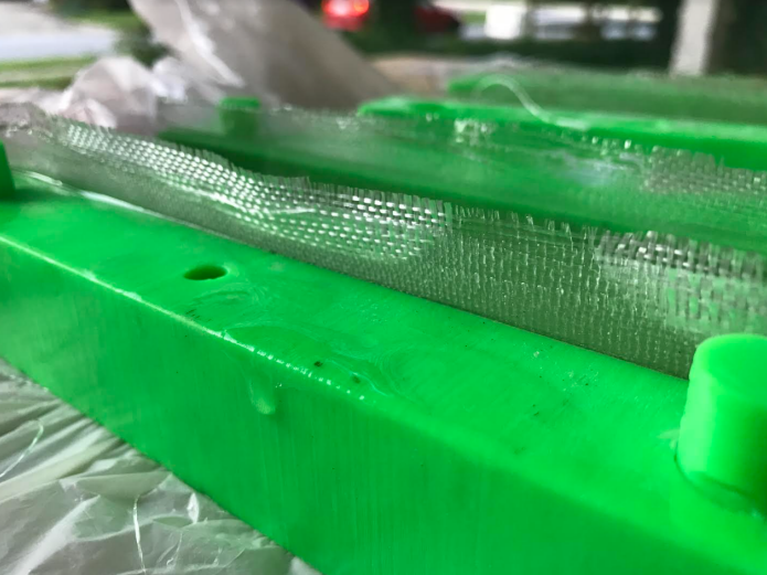
Laying the fiberglass into the molds was pretty straightforward. It was very helpful to have all my layers organized ahead of time, since the wet layup was on a time constraint. I finished the layup in 15 minutes, which gave me 10 minutes to close the mold, add the peel ply, and add the balloon. My fingers were more effective than the brush at spreading the epoxy on the contours of the mold. There was not as clean of a staggering pattern as in the Easy Composites video since it was a wet layup and the fiberglass was very malleable, but some staggering was achieved. I think it is very achievable for a student or hobbyist to get a clean stagger with prepreg.
In all previous wet layups I’ve done, I always wish I added more epoxy. I finally think I added too much epoxy this time, as the pieces are much more shiny than I want, but I’l only know after the peel ply is off.
To put the mold halves together, I bent the protruding fiberglass on the extended half inward, and put the two halves of the mold together very carefully (the molds had alignment pins, a MUST). This took a few attempts, to ensure that none of the fiberglass was pinched by the mold. I then used a popsicle stick to smooth the seam with more epoxy.
Adding peel ply to the mold was tricky. I cut two pieces of peel ply, each .25” larger than the mold halves. I put the peel ply on the extended side mold normally, but I couldn’t on the lower side. Since fiberglass is smaller than the walls of the mold, the peel ply would completely cover the fiberglass, not allowing the material on the extended side to bond. Instead, I folded the peel ply and placed it in the center of the lower fiberglass. Once the mold was closed, I was ableto unfold the peel ply inside the mold with a dowel and smooth out any bubbles.
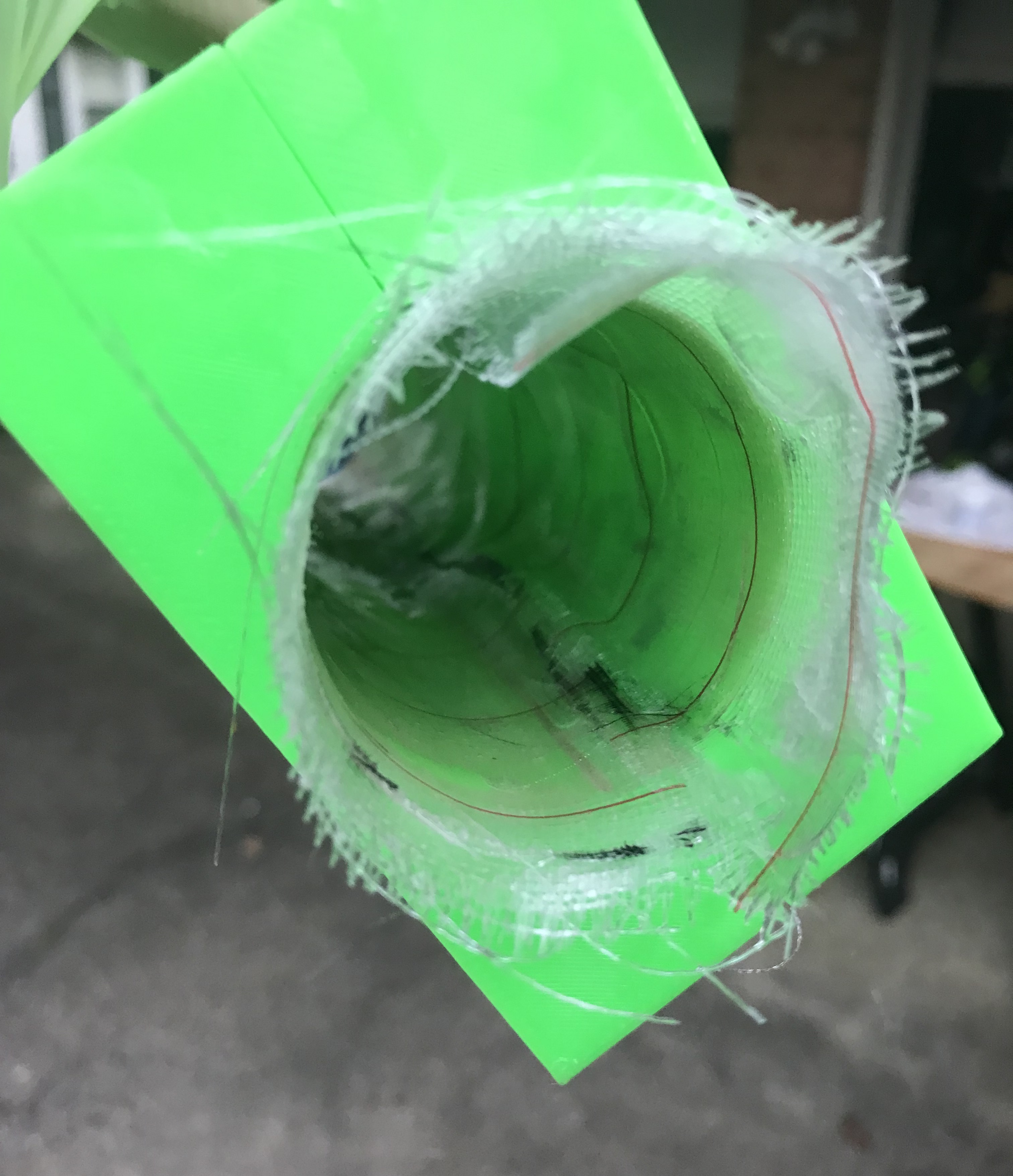
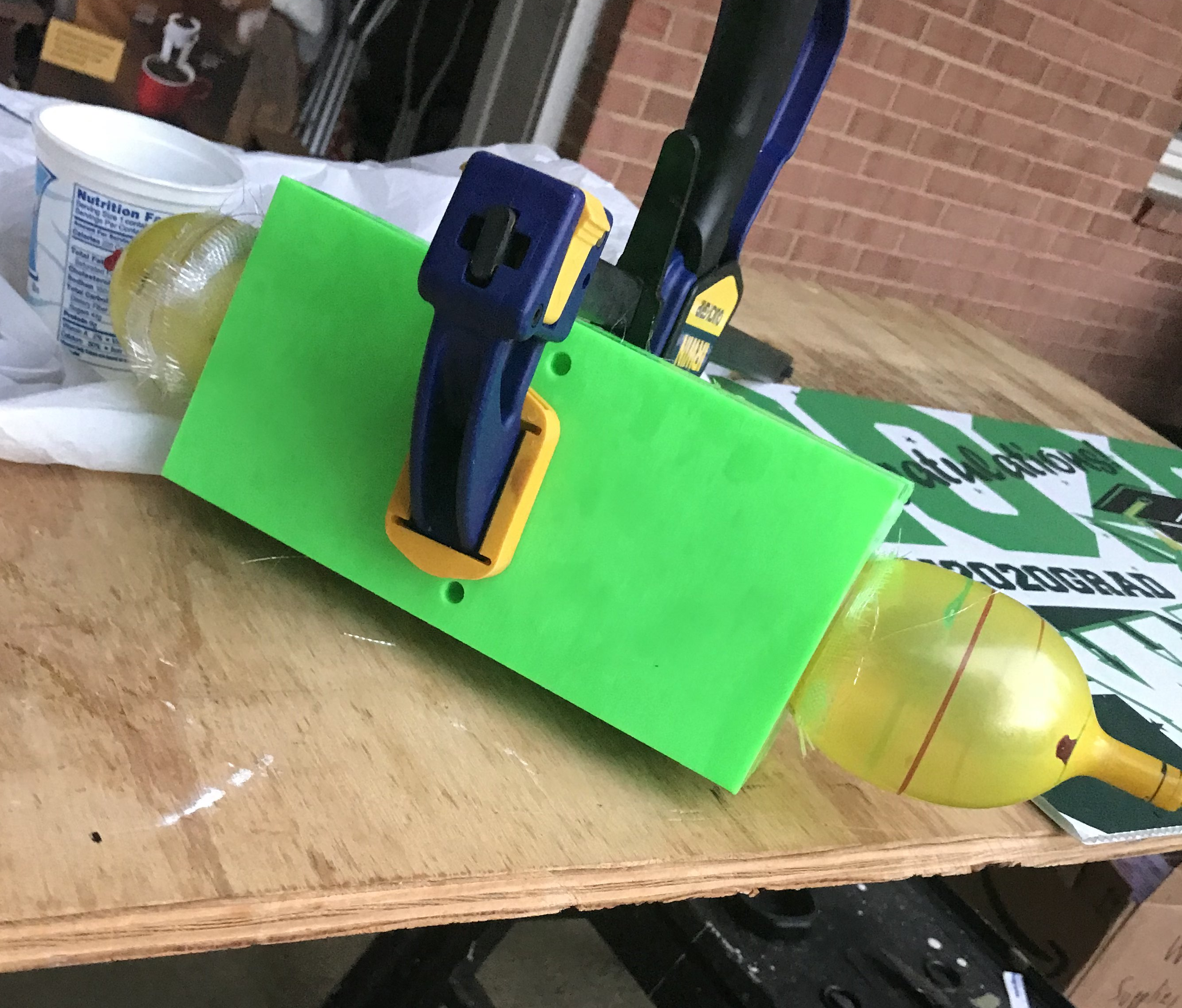
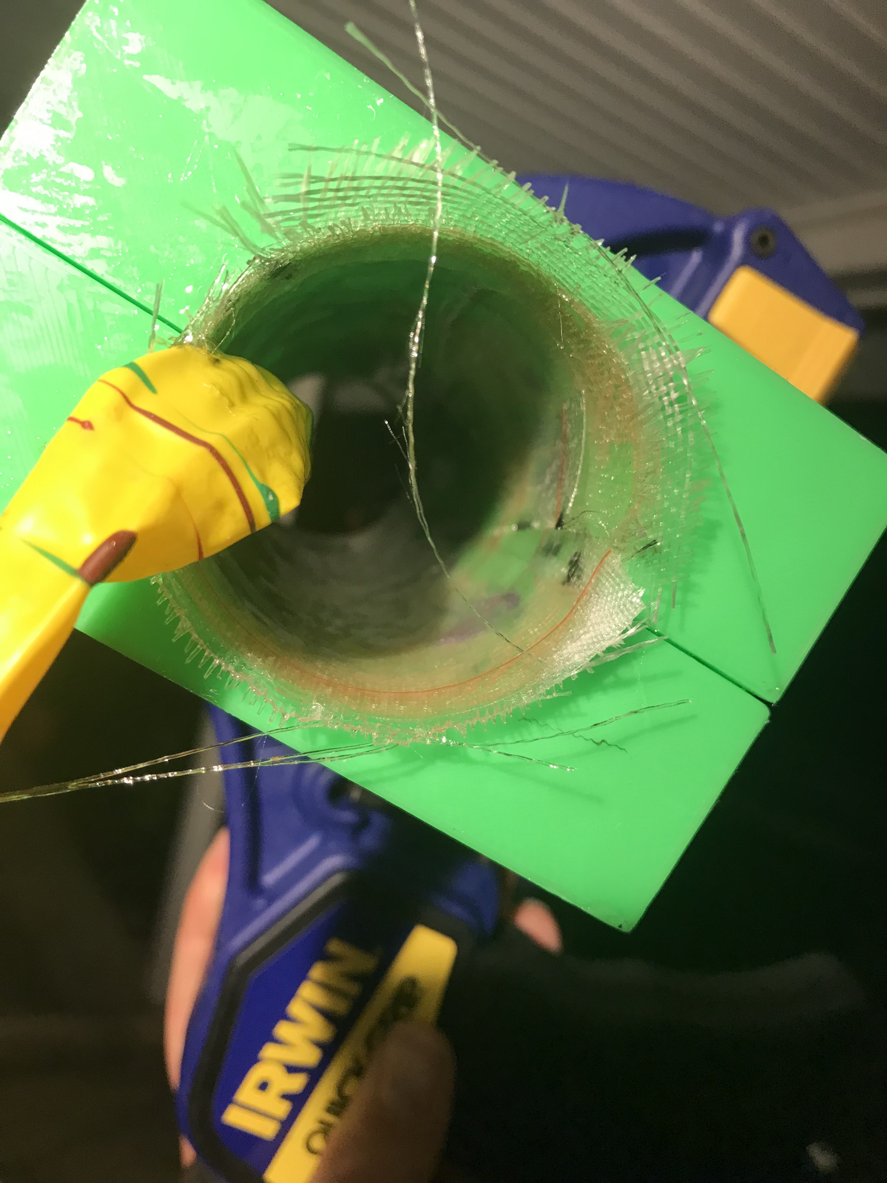
As you can see, the inside of the mold is pretty wavy at this point and not cylindrical. A large part of this is due to the folding method on the peel ply. To add pressure, I inflated a cylindrical party balloon inside the mold while the resin cured for the first hour or so. After that, the balloon lost pressure, but it left the fiberglass compressed with a smooth finish, and a clean seam. If I’m able to achieve that with a balloon, imagine how nice my finish would be with a vacuum bag
Preparing the fiberglass with this method took a lot longer, since each piece had to be individually cut, but so far the result is much nicer than the mandrel. There is yellowing on the inside of the mold, but I’m confident that it’s pigment from the yellow balloon, not a curing issue.
Mandrel Wrap
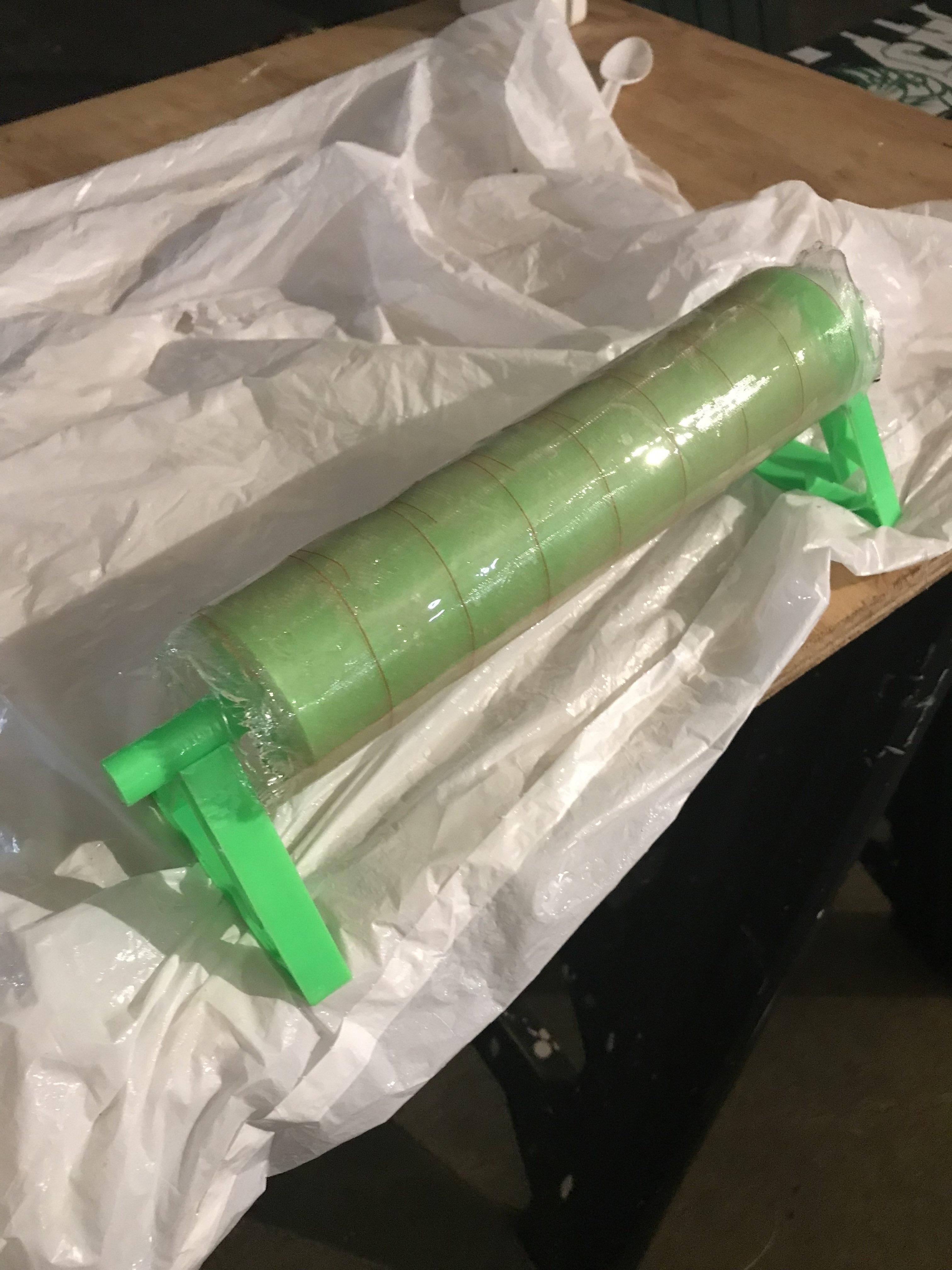
The mandrel wrap wasn’t anything special. I 3d printed a cylindrical mandrel and a (horribly designed and rushed but cool looking) holder, I wrapped 4 continuous layers of fiberglass, adding a lot of resin, and an outer layer of peel ply.
I am not applying a compressive force on this tube for a few reasons. One, I don’t have a vacuum pump, so I would have to use shrink tape, which I would need to buy. Two, It will tell me the uncompressed thickness of this particular laminate with these materials, so I can assess the performance of the mold and balloon. Third, on a large scale tube, we can’t compress a mandrel wrap without creating wrinkles, so I want to see how bad the strength knockdown is without compression. There are two noticeable bumps on the tube, where I taped the mold film to the mandrel. It shouldn’t have much of an impact on the structural performance, but it’s worth noting, especially if that’s where it fails.
What’s Next
Checking the tubes the next morning, the uncompressed mandrel has air bubbles, while the mold doesn’t, even though neither were in compression overnight.
Once these are cured, I will be running a compressive strength test of each tube. I will also try and model the staggered seam in Ansys, which might be difficult. Whichever tube more closely matches the simulation will be the method I will use for my L1 rocket. This interior molding technique can also be used for the which I was going to 3D print, but fiberglass is cooler.